|
Table of Contents
|
Make your Gen3 motherboard more like a Gen4 motherboard!
The Gen3 Motherboard has one big thing missing that the Gen4 Motherboard added: The ability to control a fourth stepper driver.
The 3G 5D Shield adds the both ability to control a fourth stepper driver for running a stepper-driven extruder such as a StepStruder® MK7 and an E-Stop connector to connect a Safety Cutoff Kit for use with a Mk6+ or Mk7 extruder.
Buy one from the MakerBot store today!
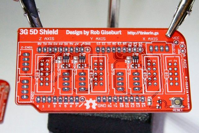
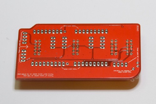
How the 3G 5D Shield works
The Gen3 Motherboard uses almost every pin available on the microcontroller, not leaving enough pins for adding another stepper driver. In order to add more pins, the three max endstop pin connectors have been rerouted to the min endstop connectors, and the three vacated pins have been used to control the STEP, DIRection, and ENAble pins of a fourth driver.
Since the circuit of the mechanical-endstops that MakerBot sells is either high or low (instead of using a pull-up or pull-down resistor) it's impossible to simply connect two endstops to the same pin without causing a short circuit. In order to prevent a short circuit the 3G 5D Shield uses AND chips to combine the two signals. Since some bots don't have endstops or only have one endstop per axis, it's possible to solder a solder-jumper on the PCB and connect endstop 1 of each axis directly to the endstop pin. The 3G 5D Shield comes in two kits: one with the AND chips installed to support six endstops, and one with the solder-jumpers soldered to support only three endstops.
Building the 3G 5D Shield kit
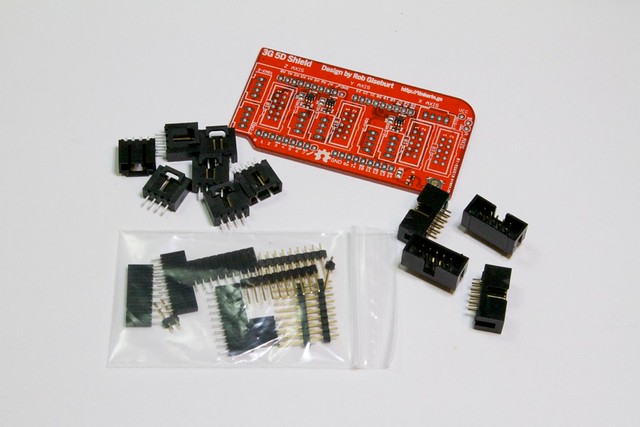
The 3G 5D Shield comes in two types of kit: one configured to support three-endstop connectors and one configured to support six-endstop connectors. Other than the circuitry that is on the PCB, the only difference between the two kits is the number of CD-ROM style 4-pin connectors.
Tools Required
- 3G 5D Shield kit (3-endstop or 6-endstop)
- Soldering iron
- (optional) Needle-nose pliers
Build instructions
Step 0
Don't believe in reading long, detailed instructions that were carefully crafted to prevent you from making any difficult-to-fix mistakes?
Ok, here's the really quick overview for experienced solderers:
- Solder the 10-pin connections. You need all four.
- Solder the 4-pin endstop connetions
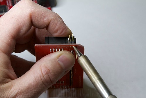
Step 1
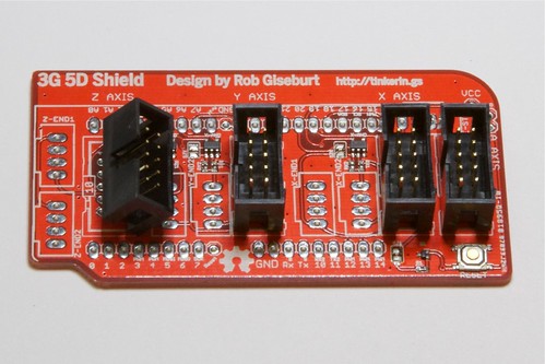
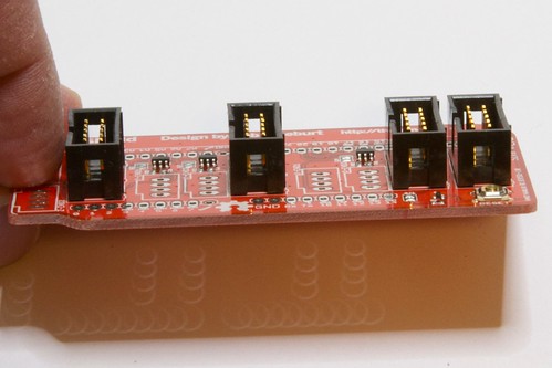
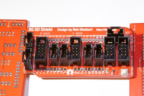
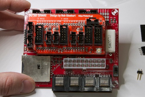
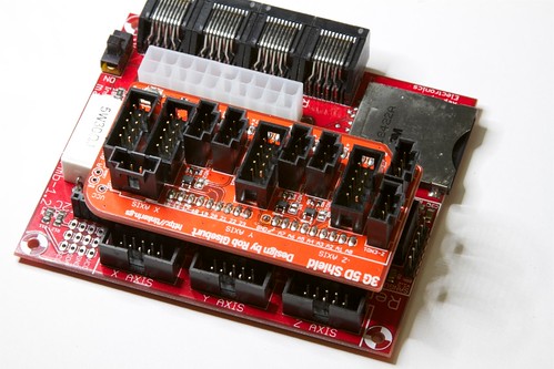
Place the four 10-pin connectors as shown, being sure to align the "key" to the "10" in a box on the PCB silkscreen. (The left one is tilted back to show the silkscreen. Don't do that.)
Place a piece of paper on top of the headers to hold them in place and flip the board and headers over, setting them down carefully. Make sure they are flush on the table.
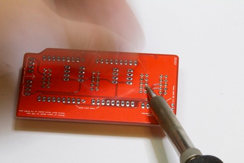
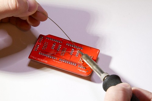
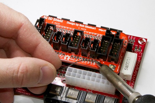
Solder one pin on each header. (Avoid the ones with the "crosshairs" around it indicating that it's a ground pin. This isn't necessary, but makes it a little faster.)
It should look roughly like this.
Flip the board with the headers over and make sure everything is lined up and level. If you need to straighten anything you can do so now. You might have to put the soldering iron on the pin to liquefy the solder while nudging the header with the other hand. (Be careful! That one pin will be HOT!)
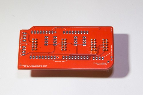
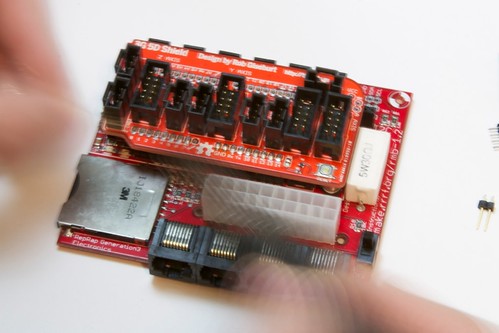
Flip the board back over and finish soldering all of the pins. The board might get fairly hot when soldering the ground pins.
It should look roughly like this.
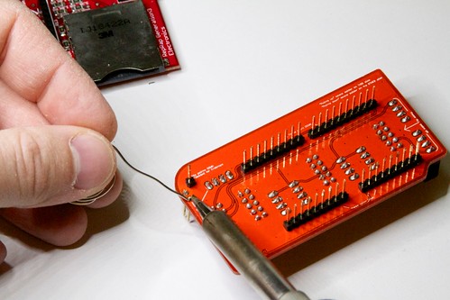
Step 2
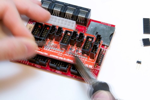
Flip the board to face up and place the 4-pin CD-ROM style connectors, being careful to make sure they face the right way. The silkscreen has a part that sticks out to match the key on the top of the header.
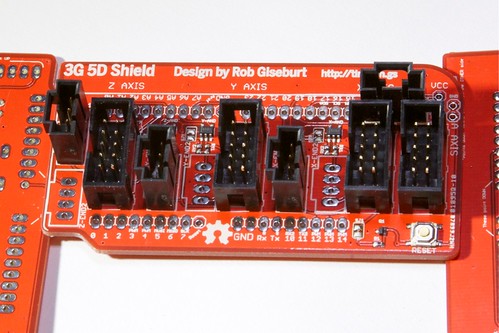
The three-endstop kits have a PCB that is only configured for the positions shown, labeled as N-End1, where N is X, Y, or Z. They are optional. You may also add the otpional E-Stop connector at the top-right.
The six-endstop kits can support connectors in any of the positions. They are all optional.
Using a piece if paper again, carefully flip the PCB over. Solder the top pins (as shown) on each connector. Flip the board over and check positioning. Fix anything that's not level and straight, then finish soldering all of the rest of the pins.
Step 3
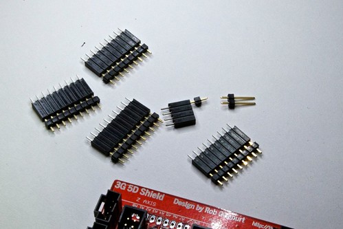
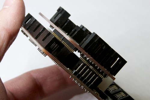
Here are the female and male headers from the kit. Go ahead and mate them up as shown unless you already have female headers on your Gen3 motherboard.
The 2-pin header doesn't have a female header to go with it.
Note: The gap shown is normal and expected.
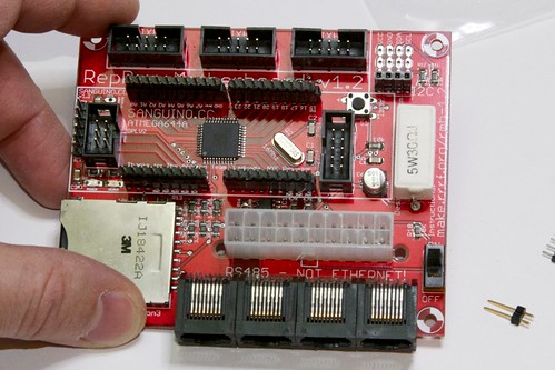
Place the 9-pin and 10-pin headers into their correct places, as shown.
Note: The Gen3 Motherboards that I had available to take pictures of already had the female headers soldered in place, so the photos will not match the instructions completely.
Don't place the 4-pin header in place yet, it'll be soldered in the next step. (This is to make it easier.)
Place the Shield onto the pins as shown. This part can be mildly frustrating since the headers are now floating loosely on the pcb and the male headers have some play in the female headers. A pair of tweezers or a toothpick might help you reach under and push the pins into place.
Once all of the pins are in their holes, press the shield down to ensure that the headers a completely seated. Make sure everything is level.
Solder one pin on each header group, then make sure everything is level again. This will be your last chance to (easily) make corrections.
Solder one side of headers.
Then solder the other side of headers.
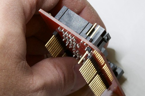
It should look roughly like this.
Now flip the motherboard, shield, and all of the headers over carefully and solder the female pins onto the bottom of the motherboard.
The extra male header pins showing is expected.
Step 3
Remove the shield with a gentle rocking motion, paying close attention to not rock it so much to bend pins. As pins begin to release it becomes easy to pull too quickly, so go slow until you get the hang of it.
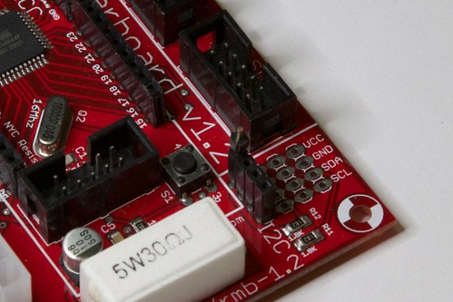
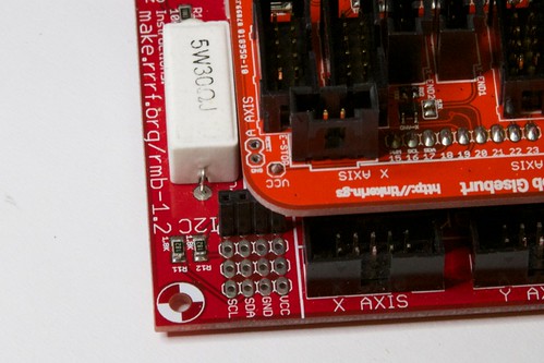
Place the 4-pin header with the 1-pin male header in the I2C column closest to the reset switch, as shown. The male header pin should be in the VCC row.
Put the shield back in place, paying close attention to the VCC pin going into the correct position.
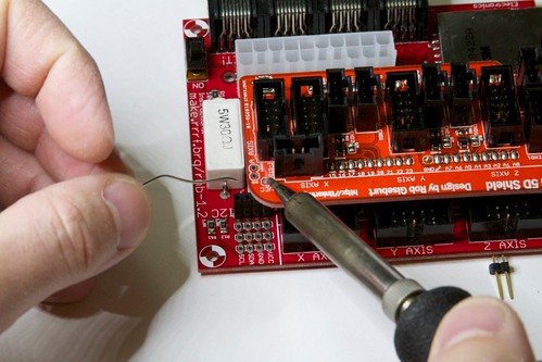
Solder the VCC pin.
Flip the motherboard over and solder the 4-pin header into place.
Step 4 (optional)
Remove the shield again. It's even more important to be careful not to bend the pins, since the VCC pin is really easy to bend.
Place it upside-down on the desk.
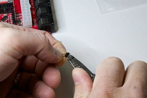
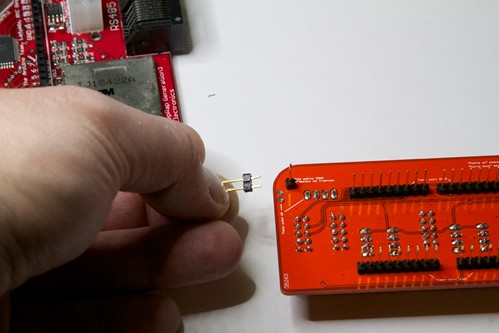
With a pair of needle-nose (or other small) pliers, gently spread the short end of the two pins of the remaining 2-pin male header apart just enough to make it fit tightly into the E-Stop/Reset output positions as shown.
Note: The 2-pin header goes onto the top side of the PCB, facing the opposite way as the VCC pin.
Place the 2-pin header in place, as shown. If the pins are spread apart enough, it should be able to hang in place.
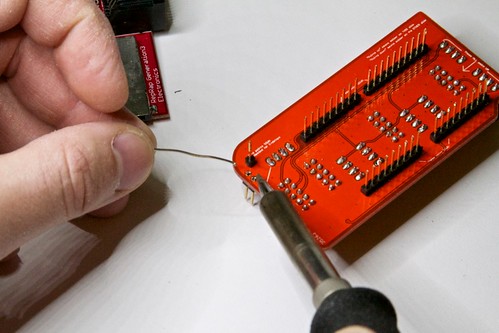
Solder only one of the two pins — preferably the one shown.
Now, pick the shield up and apply gentle pressure on the long side of the pin that you didn't solder while using the soldering iron to melt the solder of the pin you already soldered.
The pin you are soldering will get HOT. Be careful not to accidentally touch it.
You should feel the header push into place. Make sure the header is level, then remove the soldering iron and allow the solder to solidify.
Place the shield back down upside-down and solder the other pin.
Make sure you solder the first pin a little better, since it's sure to be a little low on solder.
It should look like this.
Assembly Complete
Now your shield is ready for use!
Usage
Hardware Setup
Place the shield onto the motherboard and attach the motherboard to your computer as you normally would. Attach the X, Y, and Z stepper driver cables to the marked connections ont he 3G 5D Shield instead of the motherboard.
Connect the extruder stepper driver to the A position of the shield. If you have a 6-pin connector on the extruder stepper driver, such as the one on the Gen4 stepper driver, you can use a 6-pin connector on one side and a 10-pin connector on the other, as outlined on the Stepper Motor Driver v3.4 page, and as shown below.
Cannot fetch Flickr photo (id: 5226884389). The photo either does not exist, or is privateCannot fetch Flickr photo (id: 5227479680). The photo either does not exist, or is privateYou can optionally connect Gen4 endstops at this point as well.
If you are having any trouble figuring out how exactly to wire up your 3D 5D Shield and your new StepStruder®, community member Peter Kienle has made this awesome diagram.

Software Setup
Note: This firmware should now appear in ReplicatorG out-of-the-box as a separate board called "3G 5D Shield for 3G Hardware."
- Connect the serial cable to the extruder controller (EC), disconnect the ethernet-style cable from the EC, and use ReplicatorG to upload version 3.0 or 3.1 (whichever is newer and available) of the firmware to the EC. (Note: For the EC you do not need to hit reset to upload firmare.) Reconnect the ethernet-style cable and move the serial cable back to the motherboard.
- Temporary instructions:
- In ReplicatorG, go the Preferences/Advanced and change the "Firmware update URL:" to this exact text: http://dl.dropbox.com/u/88233/3G5DShield/3G-5D-firmware.xml
- Restart ReplicatorG. Upload the 3.1 firmware that shows up to the motherboard. You must hit reset when told to to upload firmware to the motherboard. Set the "Firmware update URL:" back to: http://firmware.makerbot.com/firmware.xml
You should now have all of the needed firmware loaded.
ReplicatorG Setup
First, you should have ReplicatorG 27 or higher.
To setup ReplicatorG, you need a "Machine Type" or "driver" configuration. This is stored in an XML file, and is sometimes called a "machines.xml" file for historical reasons. I have provided a long list of example files on the Thingiverse page.
To install them:
- Grab the zip file from the thingiverse page here, and unzip it.
- Quit ReplicatorG if it's open.
- Place the resulting xml files in the "machines" folder of your ReplicatorG folder.
- Open ReplicatorG.
You should now have a long list of 3G 5D … machine types in the Machine -> Machine Type (Driver) menu. Choose the one that best describes your setup. Use the ones with (RPM) in the title with Skeinforge 35, and the ones without (RPM) in the title for Skeinforge 40+ (with the Dimension plugin).
If you have a different extruder than one of those listed, you will need to edit the stepspermm="…" attribute (or the scale="…" attribute, which is a synonym) of the <axis id="a" … > element. It is vital that this attribute be accurate, and indicates the number of steps (including microstepping level and gear ratios) that will result in one mm of filament being fed into the extruder.
Skeinforge Profiles
The only difference from the Thing-O-Matic profiles for the appropriate skeinforge version is the start.gcode and end.gode files, but to get you started I have uploaded a few on the thingiverse page. You can download them from here, and they include profiles for Skeinforge 40+ and 35. To install a profile, move the profile folder (not just the contents) to the appropriate location for your OS:
Windows: /Users/\[USERNAME\]/.replicatorg/sf_\[VERSION\]_profiles/
OS X or Linux: ~/.replicator/sf_\[VERSION\]_profiles/
On OS X, to see the ~/.replicatorg/ hidden folder, select Go to Folder… from the Go menu in the Finder, and type (or copy & paste) ~/.replicatorg/ into the dialog that comes up, then click Go.
You should now be able to use your Gen3 motherboard just like it's a Gen4 motherboard. Enjoy!
Alternatives to the shield — the cable hack
See the Thingiverse page for now.
How the shields are tested
This has nothing to do with use of or assembly of the shields, I just thought it would be interesting to share how I test each PCB after I solder the SMD components. This technique is taken directly from this tutorial by Adafruit/Lady Ada.
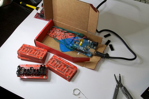
Here is the test rig with some ready-to-test PCBs, along with the shield that was put together in these photos.
The RGB LED starts out off, with the Arduino's Pin13 LED on to indicate that it's ready for a new test. (I put some Kapton tape on the RGB LED because it is bright and it was starting to hurt my eyes.)
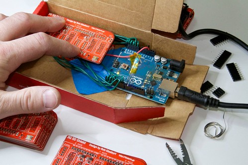
I carefully place a PCB into place over the pogo-pins and press down. One of the pins is placed slightly lower than the rest and two pin positions that are connected on the tested-PCB act as a switch for the Arduino to know when to start testing.
The Arduino starts testing the circuitry up to the switch-test, logging the results to the serial-console, then the RGB LED turns Blue to indicate it's ready for the reset-button test.
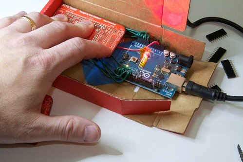
I then push the reset button. If the reset button worked the RGB LED will immediately turn green or red.
Green means all pass.
Red means I need to look at the console to see what failed. The console will show me exactly which pin failed, and in which way.
Of all of the 110+ shield PCBs I've made so far, I've had only five show a failure. Four of those were a quick fix with a soldering iron and then they passed. The one that couldn't be fixed was actually an error in the PCB fabrication.