Introduction
This page is a tutorial and resource list on configuring skeinforge.
|
Table of Contents
|
Guidelines For Contribution
If you find something in this page that could be expanded, explained better, or improved, go ahead and make it better. If you have a tip, hint, or fact that worked for you and might be useful for others, add it with your initials in front, like so:
NA: This hint worked for me and might be useful for you.
Hopefully this will help keep everything clear, while making it easy for people to add their thoughts.
Tutorial
This tutorial assumes that your makerbot has been properly assembled, ReplicatorG and Skeinforge have been properly installed, and that your extruder works correctly.
Unless otherwise noted, this tutorial is based off of the 0005/0006 versions of skeinforge.
Y: As of ReplicatorG version 0017, in order to edit your Skeinforge configuration, you should:
- Open ReplicatorG
- Load up some model (from an STL file)
- Press the "Generate GCode" button (on the right side of the window)
- A window will pop up with a profile selection section, choose "Manage Profiles".
- Select the relevant profile and press "edit" or if you wish to create a new profile from scratch, press "create".
- In order to actually test the profile after you made some changes, simply press the "Generate GCode" button again and select the profile you changed.
Prerequisites
Before we can start printing we need to set up some things.
Extruder
Thermistor Temperature Profile

There are two types of thermistors (temperature sensors) distributed with the Makerbot: the original 3mm sensor (pictured on the right), and the newer 1mm type. Both types perform the same; however, they have different temperature profiles. (By default, the extruder comes set for the 3mm sensor. If a 1mm sensor is used with this profile, the reported temperature will be about 20C higher than the actual temperature.) Before we can configure skeinforge, you must ensure that your thermistor temperature profile is set correctly. This is easy in ReplicatorG 0012 or newer.This page will show you what to do.
Extrusion Temperature
Most people have found that a temperature around 220C (for ABS) is good, but your ideal setting may be slightly different (depending on how closely your thermistor's reading matches the actual temperature). The extrusion should flow smoothly out of the nozzle, and should have a smooth surface. If the temperature is too low the extruder will have difficulty extruding and layers will not adhere properly (resulting in a weak object). A temperature that is too high will result in a rough and crispy extrusion. Using the control panel, set the heater to your desired temperature and the motor speed to 255. When the heater is at temp, set the motor direction to forward. Observe and repeat until you get a good extrusion.
To set the temperature: open up skeinforge, and open the raft dialog. Set "Temperature of Shape Next Layers" to the temperature you found with the control panel (hereafter referred to as the 'operating temperature'). We will revisit the Raft module later, but for now set "Temperature of Shape First layer Outline" and "Temperature of Shape First Layer Within" to the operating temperature. Set "Temperature of Raft" to about 15 degrees less than the operating temperature. Finally, to avoid unnecessary delay, set all the temperature change times to zero.
Extrusion Speed
Although the extruder motor PWM can be adjusted anywhere from 0 to 255, the extruder will only run with values greater than around 200. Furthermore, at lower speeds the motor will not have torque to spare, and extrusions will be somewhat inconsistent.
For now, set the PWM value to 255. This will give the best results, and you can always change it later. Open up the Speed settings in skeinforge, and make sure the "Flowrate Choice" option is set to "PWM Setting". Then set "Flowrate PWM Setting" to 255.
Unnecessary Modules
To keep things simple, deactivate skeinforge modules until you need them. Using the check box in the upper left of the dialog, deactivate the following:

- Cool
- Hop
- Oozebane
- Stretch
- Unpause
- Comb
- Multiply
- Polyfile
- Wipe
NA: If you eventually decide to use Hop or Tower, be aware that they are buggy and will sometimes cause skeinforge to crash. When skeinforge crashes it returns to the menu without producing gcode and outputs an error on the console. Also, if there are more than two towers in a part, tower occasionally tries to move the head through a previous tower, so watch for this in skeinview.
Fill

Before we can configure the fundamental settings of the extruder, we must set up the fill so that it will show when the settings are slightly misconfigured. (You will use the infill on the solid surfaces of the object to tell if the settings are correct. The correct configuration will produce a fill with no ridges (too much plastic) and no holes (too little plastic).) These settings also have the effect of making the object watertight and strong, so they are generally a good idea.
To make the object watertight, open the Fill dialog, and set "Solid Surface Thickness" to 3. (This setting sets how many layers the machine will make solid when building the tops and bottoms of objects.) Next, set "Extra Shells On Sparse Layers" to 2 or more. (This controls how many layers of plastic make up the sides of the object.) Set "Extra Shells on Base Layers" to 3, and "Extra Shells On Alternating Solid Layers" to 1. (Counting from the bottom of a group of solid surface layers, the odd layers in the series of solid surface layers will have Base Layers # of Shells, and the even numbers will have Alt. Layers # of Shells.)
Setting the number of shells on the base layer and the number on alternating solid layers to different amounts causes the machine to print several lines of plastic over the edges of the solid surface infill. This closes minute gaps in the infill, and makes the object totally watertight.
You should also set the "Infill Pattern" to "Grid Rectangular", as it will make it easier to calibrate the machine. (There will be gaps in the junctions of the fill if there is a problem.) Later on, you can set the infill you most prefer. Keep in mind that the "Line" option takes the least time to print, "Grid Hexagonal" takes the most, and "Grid Rectangular" is in between.
NA: I do not recommend you use "Line", because it is not as strong as the grid options. I use "Grid Rectangular". It's quite strong, but doesn't take much more time than "Line".
TRM: Once you have moved to a heated build platform, even very sparse infill is extremely strong. Infill becomes mostly about supporting the top solid layer of an object. Unless you are building a very large object and/or one that need very high strength (such as an extruder block). With heated builds, line infill works very well. If you want to add strength, more solid layers and extra shells work very well, plus they add strength to key features like holes (something higher infill doesnt do as much).
Raft
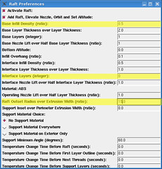
The Raft module creates a raft of plastic below the object that holds it down (preventing it from warping) and makes an even surface to build on.
NA: By default, the raft module creates two layers: a thick Base layer on the platform and a thin interface layer between the Base layer and the object. I have had nothing but trouble with the interface layer. I've found that it is absolutely impossible to remove from the object (which negates its original purpose of providing a very smooth surface on the bottom). On large prints, the interface layer delaminates from the base layer, ruining the object. Turning the interface layer off solves these problems, and the object quality doesn't suffer at all. To turn off interface layers, set "Interface Layers" to zero.
Obtaining a high quality raft is an art, but an easy one to learn. While the raft is being laid down you should adjust the z axis pulley to the correct height. (Because you can easily adjust the z axis at the beginning of a print, you do not have to set the zero position exactly when starting the machine.)
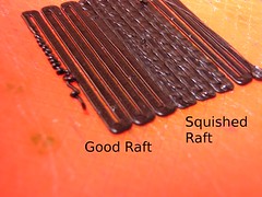
NA: I've found that the best rafts have the extrusion squished flat (but not so much that the texture of the platform shows through) with a small gap between the rows. A chisel is very helpful for removing the raft and object. To remove the raft from the platform: place the chisel under the edge of the raft and twist. Do this all along the serrated (where the extruder changes direction) edges, then insert the chisel deeper and twist as necessary. The object and raft should pop off. Peel the raft off of the object, then place the side of the object on a table and scrap off the remaining raft pieces.
Getting the raft to adhere can be difficult. If you are having problems, try increasing the temperature of the raft. Also try increasing "Base Layer Thickness over Layer Thickness" by a few decimals which makes it go slower on the raft. A last resort is to crush the raft into the build platform so that the pattern of the lines of the platform shows on the top of the raft. Be warned, however, that this will cause the raft to bond with the platform, meaning that every bit of the raft will have to be chiseled off separately.
If too much plastic is getting in the way of a good raft, decrease "Base Infill Density". If too little plastic is being deposited, increase "Base Infill Density". As you tune the layer height, feedrate, etc. you may have to change this parameter.
The last important parameter for the raft is "Raft Outset Radius Over Extrusion Width", which controls how far the raft sticks out around the object. A larger raft means less warping, so this value should be kept around 15 when possible. Large objects may require you to reduce this value to make them fit on the platform.
Several useful resources on the Raft module are:
http://blog.thingiverse.com/2009/07/14/skeinforge-quicktip-the-raft-part-1/
http://blog.thingiverse.com/2009/08/04/skeinforge-quicktip-the-raft-part-ii/
Fundamental Settings
The fundamental parameters that control objects are:
- Layer Height
- Location: Carve. This controls the thickness of each layer. A good value is .35 mm.
- Flowrate
- Location: Speed. This is the speed that the plastic comes out of the extruder. It's best to set this at the maximum (255), because lower speeds can lead to irregularity in the extruded filament.
- Feedrate
- Location: Speed. This is the speed that the build platform moves past the nozzle. For now, a good value is 25mm/s.
- Extrusion Width
- This parameter goes by several names, and there is some debate on how the different setting are related.
The first three of these parameters (Layer Height, Flowrate, Feedrate) directly control physical aspects of the object. The fourth (Extrusion Width) informs skeinforge of the width of the extrusion, and controls placement of lines of plastic. Extrusion Rate is actually separated into 3 separate settings: "Extrusion Width Over Thickness" in Carve, "Extrusion Perimeter Width Over Thickness" in Inset, and "Extrusion Diameter Over Thickness" in Speed.
Y:
Carve->Extrusion Width Over Thickness is responsible for the density between the lines, here is a picture of that option set to 5.0 (which is way too high):
Inset->Extrusion Diameter Over Thickness is responsible for the density between the border lines, here is a picture of that option set to 5.0 (which is way too high):
NA: There are differing opinions on how the different width settings should be set. Some people [I am so sorry, but I have forgotten who you are! Please fill in your name.] believe that the Diameter over thickness is the diameter of the extrusion into the air, and the Width is the width of the extrusion when deposited on the object. Personally, I've had good results setting them all to the width of the filament deposited on the object. In the interest of simplicity, I recommend you do so as well while setting up.
When setting up skeinforge for the first time, your objectives are to get strong layer adhesion and give skeinforge accurate data on how much plastic is extruded. There are differing opinions opinions on how to go about configuring the extruder.
- You can set the physical parameters (the first three in the list) to reasonable values and then adjust the extrusion width until it gives good results.
- Or, you can set the Extrusion width first and adjust the physical parameters until it gives good results.
The reasoning behind the second method is that it ensures good layer adhesion, because the filament will always be firmly squished down onto the previous layer (which occurs when the extrusion width is greater than 1).
NA: Personally, I prefer the first method, because I can set the physical parameters to what I want. I've found that as long as the extrusion width is greater than 1.5 layer adhesion will be fine.
The procedure for calibration is to set the settings to reasonable values and print a test object, them adjust one setting and print again. Don't adjust the extruder flow rate, because it is imprecise and low flowrates can cause problems. You will need the test object: a 20mm cube. Refer to the images below, and adjust your chosen parameter accordingly.
Y:
I used this square model for my first steps of calibration since it is much faster to generate, after being done with that, its possible to continue with the 20 mm cube.
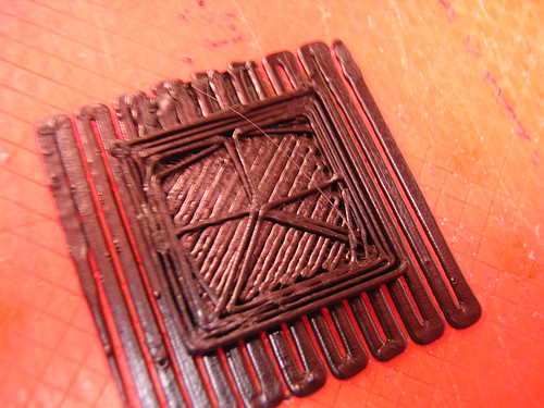 |
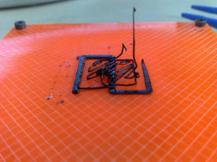
| Less plastic than expected - DECREASE Chosen parameter. |
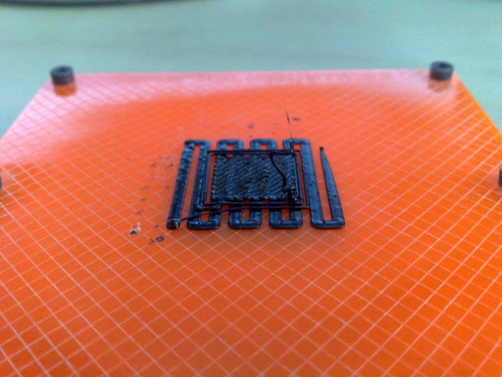
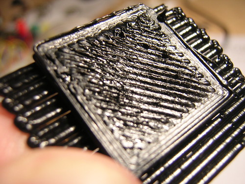 |
| More plastic than expected - INCREASE Chosen parameter. |
The goal is a solid surface infill with no gaps and no ridges. How much time you want to spend approaching this goal is up to you.
Congratulations! You've configured the essential parts of skeinforge! Pat yourself on the back and head over to Thingiverse and find some neat stuff to print.
Holes and Curves
If you've printed parts with holes in them, you've probably noticed that small holes turn out smaller than they should. There are two things that cause this: one is due to the limitations of the makerbot electronics, and the other is due to the nature of FDM (Fused Deposition Modeling, called Free Form Fabrication by the RepRap project to avoid trademark trouble).
The Geometry Problem
The Makerbot electronics, being a non-imaginary (non-perfect) computer, has an upper limit on the speed it can process gcode. This upper limit comes into play when creating small holes. Every vertex that defines a hole creates an extra command of gcode, and every command of gcode incurs a small delay. Normally this delay is not noticeable, but if a hole is defined by too many vertices the slowdown will be dramatic. (It is an annoying fact a small hole will not only have a greater slowdown (smaller travel=less time to process gcode) but that the eventual excess plastic will have a greater deleterious effect.)
TRM: All of this is also true of any curve.
Using fewer vertices on holes and printing from an sd card (the sd card is faster and has less latency than the serial connection) alleviates this problem. For holes smaller than 4 mm in diameter, no more than 8 vertices should be used. A general rule of thumb to calculate the maximum number of vertices is that there should be a maximum of one vertex per mm of circumference.
Unpause
The Unpause module tries to cancel out the gcode processing delays by speeding up the feedrate.
Whilst it is optional, (and future electronics may well make it obsolete) and highly optimized design (with low vertex count holes and curves) removes the need for it, many of the STL files out there on thingiverse are not optimized in this way. The RepRap Mendel files, for example, produce better prints when Unpause is on.
Please note that when using higher feedrates the speedup applied by Unpause can make the machine to go faster than it should. This will cause the motors to skip steps and the print quality to be adversely affected. Be vigilant.
TRM:Some find this [Unpause] to be critical to producing usable holes and curves (even when printing from SD card), the default settings work well. However at higher speeds you might have issues (the first outline of holes being pulled into the hole). Try setting the maximuum speed ratio to 1.3
The FDM Problem
When plastic is laid down around a circle, more plastic will be deposited on the inside than on the outside. This results in the inner diameter being smaler than it should be. The circle's radius be made large to compensate.
This page explains it better: http://reprap.org/bin/view/Main/ArcCompensation
Stretch
Because stl files know nothing of circles, the task of compensating these radii is considerable more difficult and imprecise. Here to perform this task is the Stretch module.
"Perimeter Inside Stretch Over Perimeter Width" is probably the most important value, if your holes are too small then this will make them bigger! Just enter a larger or smaller value depending on if your holes are too small or too big!
TRM: This works on vertical holes, because skeinforge works layer by layer, Horizontal holes would need redesigning (it doesnt see them as holes). Holes at an angle (somewhere between horizontal and vertical) may give strange results.
NA: Horizontal holes (that is, holes/tunnels with their axis horizontal) shouldn't suffer from shrinkage, because they are made of multiple layers. The filament does not go in a circle made and no excess plastic is deposited. (Each slice is a straight line that will be compensated correctly for the filament width.)
Oozebane and Friends
One of the most annoying problems with the fdm process is ooze (also known as strings or webs). Ooze is the blobs and threads of plastic left behind when the extruder leaves the edge of an object. Besides looking ugly, these strings can also weaken the object, because the extruder will have a void where the strings pulled out plastic, and so less plastic will be deposited for a short distance when the extruder starts up again.
Prevention in Hardware
One of the earliest attempts to prevent ooze in hardware was the polymer valve on the original reprap extruder. It seemed to work alright, but was complicated to make and thus not widely implemented. Thankfully, it has been made unnecessary by the pinch wheel extruder, which is capable of much faster flowrates.
The default makerbot firmware implements a valiant attempt to mitigate ooze. When the stop command is given, it runs the motor in reverse and then forward for a set time before stopping.
NA: Although this helps with ooze when the machine hasn't been configured, it becomes a problem if you want to use oozebane.
The Great and Final Victory over ooze occurred on the 2nd of November 2009. Nophead and Erik de Brujin configured Nophead's stepper motor based extruder to reverse quickly for a short distance at the end of a path and go forward quickly at the beginning. This totally eliminates oozing, but requires a stepper motor based extruder.
NA: I tried to replicate Nophead's results with the dc motor based makerbot extruder. I configured the firmware to just reverse and not go forward before stopping. Them I added a delay whenever the extruder turned on, to give it time to catch up. Unfortunately, the delays made building complicated objects slow, so I didn't pursue it further. If anyone wants to try it, here's the shell script I used to add the delays to the gcode file: extruderdelay.sh.
Prevention in Software
Oozebane
The Oozebane module attempts to control ooze by incorporating it into the object. It uses a mathematical model of the extruder to slow down the feedrate at the end of a thread, keeping the extrusion width normal. It also turns on the extruder early, to give the extruder time to make up the deficit in the melt chamber. When properly configured, oozebane can almost eliminate threads. However, it is not perfect, and inferior to the physical stepper pull back (nophead's) method.
Unfortunately, the default skeinforge settings are hideously broken for the Makerbot. Also, the documentation is hopelessly ambiguous as to the exact formula used to calculate the slowdown. (NA: My poor attempts to examine the skeinforge code for the calculation have been unsuccessful.)
The Makerbot Extruder
NA: Some people say that reconfiguring the extruder isn't necessary, so you may want to first try to configure oozebane without reconfiguring the extruder.
Before oozebane can be configured the reverse-forward maneuver that the extruder performs by default should be turned off. If left on it will wreck oozebane's model of the extruder and cause large, noticeable gaps between threads that are in line with each other (normally the gaps are filed by the ooze).
Firmware 2
As of firmware v2 and ReplicatorG 0014, it is no longer necessary to recompile the firmware to adjust the reverse and forward times. Just open the Machine->Onboard Preferences dialog with your makerbot connected.
Older Versions
NA: I've heard that people have been getting good oozebane results without reconfiguring the makerbot firmware. Because compiling the firmware can be difficult and frustrating, you may want to try configuring oozebane without modifying the firmware.
To turn the maneuver off, the extruder firmware must be recompiled. First, install arduino. Then, get the makerbot firmware form here: [http://github.com/makerbot/G3Firmware]. Follow the readme.txt in the firmware.
Once that is done, fire up arduino and open the ArduinoSlaveExtruder project. Edit Configuration.h (rename Configuration.h.dist to Configuration.h if necessary) and set MOTOR_REVERSE_DURATION and MOTOR_FORWARD_DURATION to zero.
Disconnect your extruder from the motherboard connect the usb-ttl cable to it. Click upload in arduino and press and hold the reset button on the board. Let go of the button when you see the "Binary Sketch Size" message. If it doesn't upload the first time try again.
You're done. Reconnect the extruder to the motherboard and connect the usb-ttl cable to the motherboard as well.
Configuring Oozebane
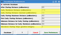
- Early Shutdown Distance
- This stops the extruder motor before the end of a line, the right value will prevent both blobs at the end of lines and strings between objects.
- Early Startup Distance Constant
- This is the most important setting. It controls the mathematical model that skeinforge uses to slow down the extruder at the end of a thread and start it early.
- Slowdown Startup Steps
- How many speeds to use when starting and stopping the extruder.
- Early Startup Maximum Distance
- The maximum distance before the start of the thread that the extruder can be turned on.
- Minimum Distance for Early Startup/Minimum Distance for Early Shutdown
- The distance that the extruder has to travel before these tools actually kick in. These values can help if you are having issues with small features.
- After Startup Distance
- This is the distance that the extruder will move slowly after starting, to give the extruder time to get up to speed.
- First Early Startup Distance
- The distance before the very first extrusion that the extruder will start up. Used to make sure the extruder is up to speed when it makes the raft. TRM: This may cause strange results when using either the Raft or Raftless tools, setting it to 0 removes what that. It is not a critical feature.
The two most important parameters are the Distance Constant and the Early Shutdown Distance. The Distance Constant is the first thing that must be configured. However, the documentation is utterly ambiguous as to what the actual formula for calculating the extruder slowdown speed/startup distance is, so trial and error are the only options.
To begin configuration, set Slowdown Startup Steps to 3. Get the test object: oozebane.stl. The test object is two towers connected by a thin base (so it will always process correctly). Set your Early Shutdown Distance to around 10 and start trying values for the Distance Constant. For the makerbot extruder, start with values around 1. When the calibration is way off there will be strings between the towers. As you approach the correct values, the strings will disappear and you will see a lumpiness in the filament width where oozebane kicks in. When oozebane is properly configured the filament lumpiness will be small. Be sure to twiddle the Early Shutdown Distance while testing. If the Early Shutdown Distance is too small, there will be strings. If it is too large, the filament will stop too early, leaving a gap.
Both of the parameters can influence the filament, so getting the proper settings isn't as cut and dried as configuring the other modules. Eventually, though, you will find settings that work for your extruder.
After you have those two settings working properly, you can adjust the other ones. Refer to the table at the beginning of this topic for guidance.
TRM on Oozebane:
Oozebane is probably the most complex and fiddly tool in the whole Skeinforge package, its settings are not always clear and it needs adjusting whenever you change any of the speed settings (and probably other settings too!)
Whilst the extruder/firmware motor reversing does mess with the theoretical model of Oozebane, acceptable results are very acheveable with a little work.
When adjusting, the 2 main settings you need to play with at first are Early shutdown distance (that takes care of the blobs at the end of lines) and Early startup distance constant (lowering this value makes the extruder switch back on sooner, so that the extruder is extruding by the time it reaches the start of a line, its actually a ratio based on the distance the extruder travels while off).
Then you will need to adjust the Early startup distance maximum (This limits how long the extruder runs before it reaches the start of a line… it stops the extruder from trailing filament all over your print).
The 2 minimum values are to stop Oozebane from kicking in when your extruder is doing tiny moves.
I'm currently running at 26mm/s Perimeter and 32mm/s infill.
My oozebane settings are as follows:
After startup distance: 4
Early shutdown distance: 1
Early startup distance constant: 3
Early startup maximum distance: 6
First early startup distance: 0
Minimum distance for early startup: 2
Minimum distance for early shutdown: 1
Slowdown startup steps: 3
These are not perfect, I'm still getting small blobs at the end of lines and gaps at the begining(I haven't re-tuned Oozebane since I switched to 32mm/s infill). But these faults are small. These settings are mainly to give people some sort of place to start from. But the best settings for you will come from adjusting and experimenting as your extruder will not perform exactly the same as mine!
Oozebane Documentation
I have copied the source-code documentation for the oozebane module here, since it explains some of the formulas and configuration settings in more detail :
Oozebane is a script to turn off the extruder before the end of a thread and turn it on before the beginning.
The default 'Activate Oozebane' checkbox is on. When it is on, the functions described below will work, when it is off, the functions will not be called.
The important value for the oozebane preferences is "Early Shutdown Distance" which is the distance before the end of the thread that the extruder will be turned off, the default is 1.2. A higher distance means the extruder will turn off sooner and the end of the line will be thinner.
When oozebane turns the extruder off, it slows the feed rate down in steps so in theory the thread will remain at roughly the same thickness until the end. The "Turn Off Steps" preference is the number of steps, the more steps the smaller the size of the step that the feed rate will be decreased and the larger the size of the resulting gcode file, the default is three.
Oozebane also turns the extruder on just before the start of a thread. The "Early Startup Maximum Distance" preference is the maximum distance before the thread starts that the extruder will be turned off, the default is 1.2. The longer the extruder has been off, the earlier the extruder will turn back on, the ratio is one minus one over e to the power of the distance the extruder has been off over the "Early Startup Distance Constant".
(1)direct from the source, the mystery oozebane equation is :
earlyStartupOperatingDistance = self.earlyStartupMaximumDistance * ( 1.0 - math.exp( - distanceConstantRatio ) )
The 'First Early Startup Distance' preference is the distance before the first thread starts that the extruder will be turned off. This value should be high because, according to Marius, the extruder takes a second or two to extrude when starting for the first time, the default is twenty five.
When oozebane reaches the point where the extruder would of turned on, it slows down so that the thread will be thick at that point. Afterwards it speeds the extruder back up to operating speed. The speed up distance is the "After Startup Distance".
The "Minimum Distance for Early Startup" is the minimum distance that the extruder has to be off before the thread begins for the early start up feature to activate. The "Minimum Distance for Early Shutdown" is the minimum distance that the extruder has to be off after the thread end for the early shutdown feature to activate.
After oozebane turns the extruder on, it slows the feedRate down where the thread starts. Then it speeds it up in steps so in theory the thread will remain at roughly the same thickness from the beginning.
Raftless
If you have moved to a heated platform then you need this tool. (if you are printing on hot acrylic then you don't, your acrylic will be warping like mad and you need a raft to accomodate the uneven-ness!)
For people starting out with hot kapton though, this tool is the key!
Simply, you need to be moving slowly enough that you don't just pull the outlines up as you go. And you need to find a balance of flow rate so that the outline is well pushed into the kapton but doesn't end up too wide. Its also critical to be doing this all at the right Z height so that the infill works correctly.
TRM:
I'm running at a feed speed of 0.3 and a flow rate of 0.8
These are the lowest speed I can extrude at and the highest speed I can move at without pulling up the plastic (although its not 100% reliable on that score).
DD: note that the newer versions of skeinforge support first-layer feed & flow rate modifiers in Raft. If you're using a recent version of skeinforge, you can use these instead of the raftless module.
Peoples' Skeinforge Settings
This is an area to post your working skeinforge settings. Compress your skeinforge settings folder (on linux systems, /yourhomedirectory/.skeinforge) as a zip file. Please include your initials and the date you made the file in the filename. DO NOT POST THE CONTENTS OF THE FILES ON THIS PAGE! It just makes them more difficult to use and takes up a stupid amount of space.
To post the files, please make a level 5 section header (so the sections are unobtrusive) with your name or initials. In your section, include:
- What version of skeinforge the settings are for
- What type of plastic(s) the settingbes are for
- Where your start.txt expects the extruder to
- Any notes you have about what is configured well, what to watch out for, etc.
Then attach your file to the page with the link at the very bottom and post a link in your section. (Hint: look at someone else's section while editing to see how to link the file.)
Before You Use Someone's Configuration…
Set their temperatures to what works for you, because everyone uses different temperatures. Be aware of where their start.txt expects the extruder to be before you print.
Nick Ames
Skeinforge 0005, Black ABS. The extruder should be 10mm above the center of the platform. I have oozebane configured well, so this might be helpful for people who are having problems.
Download (April 17th 2010)
Tavis Hord (sideburn)
ReplicatorG 0019, Natural ABS. Heres my latest set of profiles. One is set to a .35mm layer thickness, the other is set to .2mm layer thickness. I have included a version that prints with a solid grid infill and another with a hollow infill. Also included are versions for the heated build platform.
Download (Oct 2nd 2010)
Resources
Skeinforge Settings
The Skeinforge documentation is a good reference.
Skeinforge not working? crashing? glitching? bad startupcodes? Try this, (provided youre on a mac) open up terminal, type in EXACTLY (you could really screw up your computer if you type it wrong so copy/paste minus the quotation marks of course) "rm -rf ~/.skeinforge". THEN, go to finder, and type in "skeinforge.py" and delete EVERYTHING associated with that. I also typed in skeinforge and deleted everything that showed up too. I did the same with python but im not sure if that would do anything. Re install python (if you deleted it) then re-install skeinforge (unless you know how to get the warmup commands to run on 0007, INSTALL 0006!!). That should do the trick! -Conrad
Skeinforge settings reference (for the newer version of skeinforge, but still useful): BfB skeinforge wiki
Calibration
A detailed write up of how to calibrate your skeinforge settings (layer thickness, speeds, ratios, etc.) to achieve accuracies of 0.01 mm. [http://rapmanv3.blogspot.com/2009_09_01_archive.html]