|
Table of Contents
|
Assembly
Estimated build time: 2 hours.
Tools You'll Need:

- Wire cutters
- Wire strippers
- Soldering iron
- Scissors
- Needle nose pliers
- M3 and M8 hex keys
- M3 and M8 wrenches or an adjustable wrench
- Super glue
- Acrylic glue if you have it
- A knife
Parts You'll Need
Nuts and Bolts

Lasercut Parts

Custom Bits + Motor

Partlist
Parts You Won't Need
The plastruder kit contains a few more pieces than most users will actually need. In particular, your kit may contain:
- An additional idler wheel. Overtensioning your idler wheel can cause it to crack or break; we include a spare so you can replace it if it gets damaged. You can also use it to build a double-idler wheel (see below for more info).
- A RepRap Insulator Retainer plate. These are special plates for mounting the Plastruder Mk3 on a RepRap machine. If you're building a Cupcake CNC, you won't need this piece. (Likewise, if you only intend to mount your plastruder on a RepRap, you won't need the big and little dino assemblies!)
- Extra 5mm LEDs and through-hole resistors. These are included for experimenters who want to add more blinking lights to their extruders; they're completely optional.
Prep Work
The build process is much easier if you build all the sub-components first, and then assemble them all into a nice, working extruder in one shot. Things like the Dino's are easiest to make beforehand, and other things like the Idler Pulley need time for the glue to dry.
Peel off Plastic

We ship the acrylic pieces with their protective plastic intact. This prevents them from getting scratched or scuffed during shipping. Use your fingernail, a small flat-head screwdriver, and/or your teeth to catch and edge and pull the blue film off. The parts are actually clear acrylic. Both sides have the film on them.
The film often gets stuck in loop letter parts (o, p, e, etc.); you can scrape it out for a perfectly clear look or leave it in to remind yourself of high school notebook doodles during boring classes.
Weird Dinosaur
Parts You'll Need

NOTE: in later batches Weird Dino Left and Weird Dino Right are called Weird Dino Front and Weird Dino Back.
- Weird Dino Left
- Weird Dino Right
- Dino Support
- Dino Bottom Mount
- Dino Top Mount
- 7 x M3 Nuts (only 5 in kit you may be 2 short)
- 7 x M3 x 16mm Bolts (only 5 in kit you may be 2 short)
- 2 x M5 Nuts
Assemble the Parts

The dino brackets lift the extruder housing up so that you get the maximum build height possible. They are very simple t-slot assemblies. It's easiest if you slot everything together, and then insert the nuts/bolts.
First, assemble the neck of the dino. Put the left and right sides together over the Dino Support piece.
Next, plug that assembly into the Build Base. The text should be facing towards the bottom.
Assemble T-slots

Now, insert bolts into each of the t-slots. You'll also want to screw in M3 x 16mm bolts as well. Don't tighten things down yet, the dino's need to be a bit loose to fit over the extruder housing later.
Attach Bottom Mount

Now is a good time to attach the bottom mount. Use Acrylic glue here instead of super glue if you have it - you'll get a much better joint. Put a dab of superglue in the middle of the plate and snap it on over the bolt heads that are sticking out. Let it sit for a few minutes and they'll be permanently connected.
Insert Captive Nuts

The dino brackets use captive nuts to make attaching them to the base easier. Take two M5 nuts and drop them into their respective places. They may fall out, so feel free to hold off on this step until you're ready to attach the extruder to the build base.
Big Dinosaur
Parts You'll Need

- Big Dino Left
- Big Dino Right
- Dino Support
- Big Dino Bottom Mount
- Big Dino Top Mount
- 7 x M3 Nuts (only 5 in kit you may be 2 short)
- 7 x M3 x 16mm Bolts (only 5 in kit you may be 2 short)
Assemble It!

The big dino is just like the weird dino but with a different neck. Follow the directions above to build it.
Idler Pulley

The idler wheel is the part that rotates along with the filament and keeps things moving.
You'll need:
- The Idler Wheel
- A 608 skate wheel bearing
- 2 x M8 washers
- Superglue
NOTE: You may also want to consider the "Double Idler Wheel" technique. See here: DoubleIdlerWheel-WhenThingsGoWrong
and here: DoubleIdlerWheelDiscussion
The assembly instruction are very very clear that the smooth end goes into the nozzle? If that's wrong then the assembly page needs to be corrected. Mine is constructed this way and before the retaining ring broke was extruding very nicely. I'll update the list shortly now I have replacements and will be back up this weekend.
Position Idler Wheel

The first step is to position the idler wheel on the bearing in the exact right position. This is easiest to accomplish if you use two M8 washers to space the wheel off the table a bit. Position the idler wheel over the 608 bearing and push it down until it hits the washers.(Don't force it if the bearing does not want to go into the idler wheel, just enlarge the hole with some sandpaper. Forcing the bearing into the idler wheel will cause the wheel to break). Use a permanent marker to write radial lines all around the idler wheel. This will help when testing the idler wheel (below) and also in case you get extrusion slow downs later.
A bearing press (or vice with flat surfaces) allows you to put the bearing in to a much tighter fitting idler wheel without breaking it. Remember to press slowly.
Glue Idler Wheel Down

Once you have it properly in place, it needs to be glued down. Apply some superglue around the inner edge of the idler wheel to glue it to the 608 bearing. Be very careful not to get any on the inside of the bearing. You only want to glue it to the outer ring of the bearing. Let it sit for about a half hour or so.
Heater Barrel Assembly
Step 1: Gather Parts

In order to assemble the heater barrel, you'll need these parts:
- 1 x Brass Heater Barrel
- 1 x PTFE Thermal Barrier
- 1 x Brass Nozzle
- 300mm nichrome wire
- Kapton tape
- 150mm ceramic tape
- 1 x 100K ohm thermistor
- two different color wires (2 x 300mm pieces of each color — 4 pieces total). 24-26 gauge is a good size. I like using red for hot, and blue for temperature. NOTE: these are NOT included in the Plastruder kit; you must supply your own.
- some solder
- 2 x crimp-on ferrules for wire
- a multimeter
- Thin M6 nut (optional)
Step 2: Prepare the Wires
First up, you'll want to prepare the nichrome wire. Nichrome is nickel/chromium alloy with a set resistance. What that means is when you pump electricity through a length of it, it heats up. If you use the right length, and the right voltage you get simple, cheap heater. Thats what we're going to build now.
Trim and Strip the Nichrome
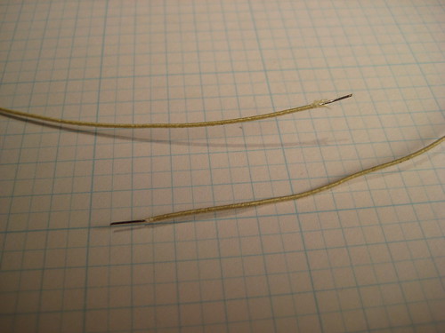
The nichrome wire should have a resistance of approximately 6 Ohm. Usually this amounts to about 300 mm of wire, but use a multimeter to be on the safe side.
Cut the nichrome wire to a length which amounts to about 6 Ohm of resistance (+/- 1 Ohm).
NOTE: It's difficult to measure the resistance of the nichrome until you strip the ends, so cut it long, then trim it down until you reach 6 Ohms.
NOTE: Make the wire too long, and your heater takes longer to heat up. Make it too short, and you burn out the MOSFET on the extruder board.
Take your length of nichrome and strip the insulation. The easiest way to do that is to use the edge of a knife and drag it along the insulation. Don't try to cut the insulation, but instead scrape it off. Scrape both sides of the nichrome wire and the insulation will easily fall away. Do this on both sides of the nichrome so that around 3mm of wire is exposed.
Strip the Heater Wires

Next, strip about 3mm from the ends of the wires you will use for the nichrome. Make sure you have a decent gauge wire as this will be carrying 2-3 amps for the heater. Its easiest if you crimp the ferrules onto this wire first. It is important you trim the exposed end of the wire to 3mm. That way it won't take up all the space in the ferrule. If you mess up, its okay. You only need 2 ferrules and we provide 10 in a kit.
The next step will depend on which crimp connector came with your kit. Some kits will contain cylindrical ferrules, and others will contain terminal crimp pins (which have a springy metal curl at one end). Follow the directions below which are appropriate for your connector.
Crimp the nichrome wire to the connector

Insert the stripped tip of the nichrome wire into the small hole in the back of the terminal connector as shown. A little bit will stick out at the top; bend it back over the connector.

Now crimp the connection by squeezing the curled end of the connector flat with a pair of needle-nosed pliers.
Crimp the copper wire to the connector

Insert the copper wire into the other end of the connector, as shown.

Use pliers to crimp the connector to the wire.
Solder the Connection

Because I don't trust mechanical connections, I like to solder the whole thing in place. Nichrome metal is pretty much impossible to solder, but the ferrule and copper wire are easy. The solder will provide a bit more stability and make the connection nice and strong.
NOTE: I had no problems soldering this. Perhaps I found it trivial to solder as I tend to use lead-free solder which behaves a little differently than the typical lead-endowed junk. That said, it's not like it hurts anything to go solder crazy on a connection like this.
If the crimp connector doesn't work for you, try this Alternate Nichrome Soldering Technique.
Insulate the Connection

You'll want to do this so that you have a wire-nichrome-wire assembly. Once you have that, then wrap a tiny bit of Kapton tape around the joint to insulate it. Your heater wire is now ready to be attached. Win!
Repeat the same process with the other end of the nichrome wire and the other piece of the same color of wire.
Separate Thermistor Leads

Next up: thermistor wire assembly. This is much easier. First, grab out the thermistor. The wires are un-insulated, so our first goal is to separate them to prevent shorts. Pull them apart so they are not touching and are separated by about 3mm. Don't pull too hard you pull it in half. The keyword here is 'gentle'.
Trim and Tin

Once they are separated, you'll want to trim the leads to a length of 25mm. Take your soldering iron and apply a bit of solder to each end of the lead. This is called 'tinning' the leads. We'll do the same thing to the wires we'd like to connect and then we'll melt them both together at the same time to make a solid connection.
In order to do that, you'll want to strip the ends off the other set of wires you have. Make sure you're using different colors than the wires for the heater! Tin the end of these wires with some solder as well.
Solder Them Together

Once both the wires and the thermistor leads are tinned, you're going to want to connect one wire to each thermistor lead. This can be a bit fidgety, so if you can weight them down with your pliers or something, it will be much easier. Place them together and heat up the solder on both of them. You may want to apply a bit more solder as you do this. When it melts, remove the heat and both wires should be soldered together.
Insulate the Joints

After that is complete, wrap a tiny bit of Kapton around the solder joints. This will keep them from shorting out and may add a bit of mechanical stability.
Isolate the Leads

Take two more short pieces of Kapton Tape and tape from the glass bead to the solder joints. The point of this is to keep the thermistor leads apart so they don't short (and give you bad temperature readings). Put tape on both sides so its completely insulated and safe, and then your thermistor is ready for action.
Step 3: Prepare Heater Barrel
Thoroughly Clean Parts
Sometimes the heater barrel / thermal barrier / nozzle will have debris from the machining process on them. You'll want to wash all of these parts in water and/or rubbing alcohol. The heater barrel especially will need cleaning. Once you've washed them, I also like to clean the barrel out with a Qtip or other long stick thing that you can jam down it to push out any debris (like metal shavings.)
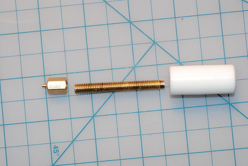
Assemble Machined Components
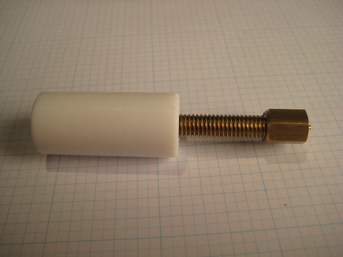
We don't want any shorts on the metal heater barrel in case the Kapton we used to insulate the solder joints falls off. The easiest way to do this is to assemble the Thermal Barrier, Heater Barrel, and Nozzle.
NOTE: Your barrel may have one end that is dressed/tapered, and one end that is simply sawcut. The "pretty" end is the one that goes into the PTFE barrier - the joint between the barrel and the barrier has to be clean and tight. As part of that, make sure that the barrel is screwed in tight, not just snug - need to make sure there isn't a gap at the top.
***NOTE: Newer barrels have one end with a smooth shoulder that is turned down to about 4.5mm for about 2mm. There has been a lot of debate about which orientation is better. Bre suggests that the end that is smooth for about 2mm goes into the PTFE, not the nozzle.
New style barrels go like this:
This is the correct way.
**Make sure you tighten the heater barrel all the way into the thermal barrier (but do not overtighten, see below). Failure to do so may cause extrusion failure due to plastic filling the gap between the heater barrel and thermal barrier.
Don't go all crazy and use a vise to screw them together either. The goal here is to make sure there's no gap inside, but not to cut into the PTFE so deeply it deforms it. If you want to be really sure, check the drawings in thingiverse and look at how they are suppose to mate inside the PTFE, and check the length of the barrel that should be sticking out. It may help to put a piece of raw filament all the way through the insulator and into the barrel while you are tightening them together. This may help you from over tightening the barrel and deforming the edge of the hole causing the opening to narrow.
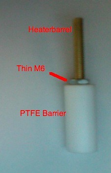
Go ahead and add the supplied M6 nut onto the heater barrel before you thread on the PTFE thermal barrier. Later, when the heater is fully put together, you will unthread the thermal barrier and the nut to add the big washer to end up with a stackup in this order: nozzle, heater, big washer, M6 nut, and finally PTFE thermal barrier. Having the nut there is crucial because it takes the load off the thermal barrier while the extruder is at temp and running. Without the nut, the threads on the PTFE thermal barrier will eventually fail because the hot heater barrel warms the plastic to the point that the force of the extruder motor will push the heater barrel out of the PTFE thermal barrier. Please note that after you are done assembling the heater in the steps below and are directed to add the big washer, don't screw the nut tight against the PTFE thermal barrier, as it will still be putting some stress on the PTFE threads. Tighten it only to the point that it just touches the PTFE thermal barrier, or even leave a small gap.
Note that if you partially disassemble this later and reassemble it in a different order, make sure the PTFE barrel top is flush with the top of the insulator retainer before you screw the assembly back onto the plastruder body. Otherwise you will crack the insulator retainer as you tighten it to the plastruder body.
Because the M6 nut modification transfers more sress from the PTFE to the insulator retainer, every builder should print a few spare insulator retainers just in case. The digital files to print are found here: http://www.thingiverse.com/thing:1004
Note: the printed ABS insulator retainer seems to be less brittle than the original acrylic one anyway.
Insulate Heater Barrel
Once you do that, put one layer of Kapton tape just below the PTFE barrier, or the M6 nut if you used one. This is where there would be a potential short, so that's where we're protecting.
Attach One End of Heater

Now we're going to attach the nichrome heater to the heater barrel, and we're going to do that using Kapton tape. First, bend a right angle into the wire connecting to the nichrome just above the joint. Then, tape that end down to the heater barrel just below the PTFE where we just insulated the heater barrel.
Wind Nichrome Around Heater Barrel

Next, you'll want to wind the nichrome wire around the heater barrel. The closer you get it to the nozzle, the better. Check the picture for a good indication of how far down the barrel to start. Make sure you wind it so the nichrome fits into the threads of the barrel. You may want to use some thermal paste here, but its certainly not necessary. I don't like it because its messy.
Note: There is some dispute as to whether you should layer the nichrome or not. Some people suggest wrapping one layer of nichrome wire. Others suggest overlapping the nichrome wire when you get close to the nozzle. ABS (the plastic you get with your kit) will work fine with either way, but PLA seems to work better with the nichrome wrapped in one layer.
Finish Attaching Heater

Once you've wrapped the nichrome around the heater barrel, carefully bring the other end back up next to the start of the wire and secure it into place with more Kapton tape.
This is a good point to check for shorts across the heating wire to the nozzle using your multimeter's resistance setting. Probe one end of the nichrome wire and touch the other probe to the brass heater barrel. It should read a very high resistance (from your body's own conductivity) or as an open circuit. If you read a low resistance you must unwrap the nichrome, locate the break in the covering and insulate it with some Kapton tape. Failing to do so could release the magic smoke from your extruder electronics.
Now you'll want to secure the whole thing to the heater barrel using a decent amount of the tape. A good rule of thumb is to use enough tape so that the heater barrel + tape is even with the nozzle.
Attach Thermistor

Now that you have the heater attached, you'll want to attach the thermistor. This is what measures the temperature, so you'll want to attach it directly to the nozzle. If you want to go super-custom, drill a tiny indentation into the side of the nozzle. If you're like me and want to keep things simple, just tape it directly into the side of the nozzle. Use one or two layers of tape, and also tape all the way up so that the leads/wires are attached to the heater barrel. It is a good idea to attach it on the opposite side of the barrel for ease of wiring.
Step 4: Insulate the Heater

This step is not strictly necessary, but it does make things look tidy, keeps your heater warmer, and gives better startup times. I'd definitely recommend insulating the heater barrel.
Trim Ceramic Tape
The first step is to trim the width of the ceramic tape if necessary. You want it to insulate most of the heater barrel, and only go down about halfway on the nozzle. You can go further down, but it is possible it will interfere with extrusion and printing techniques like towering.
Attach Tape To Barrel
Once your ceramic tape is ready to go, take a short length of the Kapton tape and use it to attach one end of the ceramic tape to the heater barrel. Wrap it around the barrel and then use 2-3 layers of kapton tape to make sure it stays connected.
When wrapping the ceramic tape around the nozzle, don't pull on it too hard as it will tear…
Finish it Up

Can you tell we love Kapton tape? It's only the raddest space-age material for building robots EVER! No big deal.
Add Retainer Washer
TIP: Before adding the retainer washer, insulate the center hole with 8-10 short strips of kapton tape. This prevents the sharp edges of the washer from cutting through the insulation on your heater and thermistor wires causing shorts, erratic extrusion, and days of frustration.

I like to save the retainer washer for last, because it makes it really difficult to do all the wrapping and rotating that needs to be done. To put it on, simply unscrew the PTFE Thermal Barrier and the M6 nut, slide on the washer, thread the M6 nut snug against the washer and then screw the PTFE Thermal Barrier Back on. Make sure you screw the PTFE Thermal Barrier all the way back on. You may have to bend the wires down a bit to make it fit, but thats okay. NOTE: Be extremely careful to make sure you are unscrewing the PTFE barrel and not the nozzle, or else you will wreck the whole assembly and need to start again. If you are worried, you can always put the washer on first. Once the PTFE Thermal Barrier has been threaded on, unthread the M6 nut a bit to back it off of the big washer and snug it gently against the PTFE Thermal Barrier.
Filament Drive Mechanism

The filament drive mechanism is a stacked assembly made up of 6 plates. These plates are laser-etched with a number in the upper left corner. They are numbered in sequence. The bottom plate is #1 and the top plate is #6. I have labeled them A-F in the pictures to make them easy to see.
Stuff You'll Need
- motor
- 1.5mm hex key
- 2.5mm hex key
- 1 M3 x 8mm bolt
- 3 M3 x 20mm bolts
- 1 M8 x 35 mm bolt
- 1 M8 nut
- 2 M3 nuts
- 2 M8 washers
- the aluminum pulley
- the 606 bearing
- assembled idler wheel
- assembled dinos
- heater barrel assembly
Step 1: Attach Pulley to Motor

The pulley is the part that 'bites' into the filament and physically pushes it into the heater barrel. Its very important that the pulley is very firmly attached to the motor shaft.
This is fairly easy to accomplish with the pulley that we use. It has two set screws that lock the pulley onto the shaft. First you should position the pulley onto the shaft properly. The set screws should be on the bottom towards the motor. The pulley itself should be close to the bottom of the shaft, and one of the set screws should be directly above the flat side of the shaft.
Screw both of the set screws down and then tighten the proverbial daylight out of them.
Step 2: Attach 606 bearing to Motor
The 606 bearing is the smaller of the 2 bearings in the kit and has a 6mm inner diameter to match the motor shaft. This bearing will take the brunt of the force from the compression of the filament during normal operation. This is one of the major improvements to the MK4 design and will lead to longer motor life and better overall performance.
Simply push the bearing on over the motor until it is up next to the pulley. If it is a tight fit (though nothing like the tight fit of the motors you encountered while building the Cupcake), you may need to gently tap it into place.
The bearing will only be partway on the motor shaft when finished, but this is fine.
Step 3: Attach Motor to Motor Mount Plate (#1)

Grab out your trusty M3 hex key and one M3 x 8mm hex bolt. You'll also need the motor and the motor mount acrylic piece. Although there are four holes, you only want to put one bolt through the rightmost hole. Line up all the holes with the motor holes and tighten it down. More bolts will go in the other holes later.
Make sure to have the wires from the motor coming off to the right towards the rest of the extruder housing as shown in the picture.
Note: Newer batches may not have this screw hole. They just rely on the 3 screws used in step 12. Just continue without screwing in this screw if there is no hole for it. Older batches may also benefit from leaving this screw out as it allows fast removal of the motor to clean chipped plastic out of the gear teeth.
Step 4: Add Spacer Plate (#2)

The spacer plate adds space to the body. It only fits on one way, so just stack it on.
Note: Newer batches may not have the hole depicted for the motor screw.
Step 5: Add Filament Guide Bottom Plate (#3)

This plate also just stacks up on top of the others. The text should be towards the top and legible from your point of view.
Step 6: Add Filament Guide Middle Plates (#4)

This is a two-part plate. There is a left side piece and a right side piece. The left side piece goes over the motor/pulley, and the right side goes over the big open space. The text should be towards the top as usual.
Step 7: Insert Captive Nuts

These nuts are very crucial for attaching the heater barrel assembly. There are two little rectangle slots towards the bottom of each fo the filament guides. Simply place one nut in each and you're done!
Step 8: Filament Plate Top (#5)

This plate fits on over the other plates. Lay it on top and you're done!
Step 9: Insert Idler Pulley

Take the assembled Idler Pulley that you made in a previous step. Put one M8 washer down on the inner area over the 8mm slot. Then place the idler pulley, and then place another washer over that. You'll want to do a quick sanity-check to make sure that the idler pulley can easily slide between the flanges on the pulley. If it does, you inserted it correctly. If not, try flipping the idler pulley over. If that still doesn't work, try juggling the washers around until you have it at just the right level.
Check the Pulley Alignment!

Once you do, make sure all the washers/pulleys line up over the 8mm slot. You'll be putting a bolt through there very shortly to keep everything in place, but until then it will be a bit wobbly.
Step 10: Attach Retainer Plate (#6)

The retainer plate is the top layer of the sandwich. Place it on the top of the stack with the text facing out and on the top. Be very careful not to disturb the idler bearing. If you manage to move them out of place, take the plate off and put them back in place.
The retainer plate is the final plate and should snap over the 606 bearing and lock it into place.
Step 11: Insert M8 Nut

Now, you'll want to put the M8 hex cap bolt through the back of the Motor Mount and then put a nut on it. You don't need to tighten it down yet, so just hand-tighten it so that nothing falls out. We'll be putting more M3 bolts on in a second, and those will align everything.
Step 12: Final Motor Bolts

Grab the M3 x 20mm bolts (there should be 3 of them). Insert them through the three holes around the 606 bearing so that they go through all of the plates to meet the motor. Use your M3 hex key to tighten them down and bolt the whole assembly to the motor. Do not skip this step.
Step 13: Attach the Dinosaurs

You'll need:
4 x M3 x 50mm bolts
4 x M3 nuts
4 x M3 washers
4 x M3 x 1/2" spacers
The dinosaurs are the parts that elevate the extruder to give you more build area. The weird dino attaches to the left of the extruder, and the big dino attaches to the right of the extruder. Make sure the dinos are loose before you attempt to attach them, otherwise you may break them accidentally.
Put the M3 bolt through the back of the dino, then thread it through the entire housing, and finally out the front of the dino. Put a 1/2" spacer over the exposed bolt, followed by a washer, and finally a nut. Repeat this for the remaining three corner holes and you'll have a mostly assembled plastruder.
Once you have everything assembled, you can tighten everything down a bit, except for the M8 bolt.
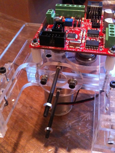
Step 14: Adjust Pinch Wheel Distance

This is one of the other major innovations in the MK4 plastruder. We tested dozens of pulley to idler distances and found that 2.0mm is the ideal distance for optimum grip strength.
Simply insert the included length of steel rod into the gap between the idler wheel and the motor pulley. With your fingers, push the pulley up next to the idler wheel and then carefully tighten down the M8 bolt while making sure that the idler pulley does not slide out of position. If you made sure to sandwich the idler wheel between two M8 washers, then you will be able to really tighten down the idler wheel without breaking anything.
Once you have the idler wheel locked into place, pull out the steel measuring stick and put it somewhere safe. If you have it the right distance, you'll feel it slide against the idler wheel and pulley as you pull it out. If there is no resistance, or if there is quite a bit of resistance, then you either have it too loose or too tight. Loosen the M8 and give it another try.

Pro tip: If you position your M8 wrench as shown in the picture, you can lightly push up against the dino in order to keep the idler wheel snug up against the pulley while you tighten down the M8 bolt with your hex key.
NOTE: This is good time to measure the small hole at the top of the PTFE barrier with calipers. If you make the idler wheel too tight, it can deform the filament stock too much and cause it to be wider than the hole in the PTFE, which can lead to extruder jams. When you start using new filament stock, it might be a good idea to put a inch or two through the pinch wheel then back it out and measure it to ensure the squished filament is not too wide to fit into the PTFE thermal barrier.
Step 15: Attach Extruder Controller Board

The extruder controller board should fit onto the ends of the 50mm bolts. Depending on how confident you are with your assembly skills, you will want to bolt it on with 0-4 nuts. If you feel like you're a rockstar and built it perfectly, use 4 nuts. If you feel like you may be taking it apart again soon, use 1-2 nuts. It will actually stay in place pretty well with zero nuts, but its not a good idea to run it like that.
Alternative Arrangement: Some MakerBot Operators will prefer to mount the controller board somewhere else. This can provide a clear line of sight with plastic as it is pulled through the Plastruder.
Some of you may not need this line of sight, but it can be extremely helpful for debugging. As you can see from the image, one option is to mount it with a bunch of hot glue (or whatever else you think is safe).
If you go with another location, just BE SURE that you're not going to have the controller crashing in to your MakerBot casing.
Attach Heater Barrel
You'll need:
- 2 * M3 x 50mm bolts
- 2 * M3 x 16mm bolts
- 1 x Insulator Retainer
- 1 x Heater Barrel Assembly
- 1 x Retaining Washer
- 6 x M3 washer
- 6 x M3 nuts
- 2 x zipties
Step 1: Fit Bolts
Take 2 M3 x 16mm bolts, and 2 M3 x 50mm bolts and put them through the Insulator Retainer piece. The 50mm bolts should go backwards through the Retainer holes near the text and the one directly opposite it (top and bottom if you are reading the text).
The 16mm bolts should go through the holes on the left and right if reading the text, but the M3 16mm bolts are too long to fit into the casing and secure the Retainer tightly. Before inserting the 16mm bolts, screw on a M3 nut all the way to the head, then, add a M3 washer. This will allow correct tightening of the retainer assembly. Be careful not to tighten these bolts too much, or you can break layer #4.
Finally, put the M3 16mm bolt through the Retainer. The additional washer and nut should enable you to tighten the Retainer properly. Also, you may want to put some M3 nuts on the end of the long bolts to keep them from falling out.
Step 2: Attach Insulator Retainer
The Insulator retainer bolts into the captive nuts in the extruder housing. Tighten them down with your fingers and then give them a quarter-turn with the allen key. Keep in mind that there is a proper orientation so that the heads of the long bolts do not cause problems with the housing and/or electronics. The short side goes towards the front.
Step 3: Attach Heater Assembly

First, thread a single nut all the way up onto each of the two M3 x 50mm bolts.
Now, Grab your finished heater assembly. We're now going to bolt it into place, so make sure there is a drilled washer between the barrel and the PTFE insulator.
The washer has holes that are not symmetrical. These line up with the bolts coming down from the insulator retainer. Slide a washer on each of the M3 bolts, then slide the heater assembly, PTFE barrier first up into place. Fit the M3 bolts through the washer and then put a washer and nut on the end of each.
Tighten it down

Rotate the nuts until they are holding the large washer snugly in place. Make sure there is no wiggle room between the extruder housing and the thermal barrier. Now rotate the nuts down from the top of the M3 bolts and tighten them all together. This will hold the whole assembly in place.

Take extra care here. If everything has gone well you should have very good alignment between the channel running down the acrylic plastruder, the PTFE thermal barrier, the brass heater barrel, and the brass nozzle. In fact, if you hold the whole assembly up to a light you should be able to see light coming through the nozzle, exactly centered in the channel. Checking this will ensure that your plastic filament has a very easy time finding the path all the way down to the heater barrel and nozzle and that your extrusion will be very uniform. If you cannot see light coming through the nozzle then you should loosen the nuts, adjust, and retighten.
Step 4: Zip-tie the Wires

This is a tidying step. Bend the wires out and around the large washer. Then zip-tie each set to one of the bolts. You can also use twisty-ties, or even a short length of solid-core wire if you do not have zip-ties handy.
Electronics: Wire it all up!
Step 1: Cut wires to length
The first step is to cut the heater / thermistor wires to length. If you forgot which wires are which, you'll want to grab out your trusty multi-meter to measure the resistance of the wires. The thermistor should read somewhere >50Kohms, and the nichrome wire should read somewhere between 5 and 10 ohms.
Run them closely along a path up to their appropriate screw terminals. Add a little bit of length to them, so that they hang over the back of the screw terminals, and then cut them to length. Now strip the ends of each of them and you're good.
Remember to twist the thermistor sensor wires around each other over the length of their path from the plastruder to their final destination. With four motors going in close proximity there will be plenty of opportunity for EMF-induced noise. Twist the heater wires together to keep things tidy.
Step 2: Insert and Secure Wires

The wires for the heater are non-polar (can be inserted in any direction) as are the wires for the thermistor. Put them in their respective holes and tighten them down. The thermistor wires should go into the block labeled 'Thermistor', and the heater wires should go into the block labeled 'B+/B-'. The motor wires are actually polar, so insert the red wire into 1A and the black one into 1B.
Plug in Extruder Controller

Finally, you'll want to plug the Extruder Controller into your RepRap Motherboard. Grab an ethernet patch cable, and you're good to go. Please note: this is not ethernet. We use these common cables to cut costs and provide a robust connection that can provide both power and communications over a single wire.
note : you may want to solder on the 180 ohm (R1) resistor near the
serial jack to properly terminate the RS485 connection, see here for details. If you're careful, a through-hole resistor from
RadioShack will do.
Test Your Plastruder
Before mounting your plastruder in your MakerBot, it is recommended that you "bench test" the Plastruder and make any necessary fine adjustments. Spend some time fine-tuning the position of the idler wheel in your plastruder.
Note: Thermistors are an analog component and can vary significantly between batches, particularly when operating at extrusion temperature. Some kits have shipped with a 1mm diameter thermistor while others have a visibly different 3mm diameter thermistor, all under one manufacturer's product code. These will likely require different calibration settings; running the plastruder without proper calibration can damage it.
For example, if your extruder is too cold the filament will not pass through the extruder and the motor will repeatedly strip filament. If the heater is running too hot, the nozzle may become clogged with oxidized ABS, or more likely your thermal insulator will melt and begin to leak plastic.
Review Adjusting the Thermistor Settings for instructions on how to calibrate the extruder settings to match your specific thermistor.
Test procedure
- Set up the Plastruder above a surface that you don't mind covering with hot melted plastic.
- Hook everything up, but don't bother to mount the Plastruder in your MakerBot body yet. This means: connect the heater, thermistor, and motor to the Plastruder controller, connect the Plastruder controller to the motherboard, and connect your PC or laptop to the motherboard with the included USB cable. (All boards should have had firmware loaded on them in previous steps.)
- Turn on the MakerBot!
- Fire up the ReplicatorG software!
- Select the Machine->Driver menu, and ensure that "Cupcake" is selected.
- Select the Machine->Control Panel menu item to open the Control Panel. You should see a pop-up window that looks like this:

- Set the target temperature to 220 degrees C, hot enough to melt ABS plastic. The heating element should switch on, and you should see the temperature shown in the Control Panel begin to rise.
- Wait until the nozzle temperature reaches 220 degrees.
- Set the motor PWM to 255 ("full on.")
- Feed a strand of ABS plastic filament into the plastruder.
- Click the "forward" button.
- The ABS plastic should now begin to feed slowly into the plastruder. Feel free to make marks on the ABS plastic with a sharpie to make the movement easier to perceive. Look at your previously done radial marks on the idler wheel. Look to see if the filament is moving down the barrel at a good rate and also how large the indentations are in the filament (see video).
- After a while, the Plastruder should begin to extrude a thin host plastic filament.
- Continue to extrude plastic for three or four minutes.
- When done, click the "Stop" button in the Control Panel. Use a hobby knife to trim the plastic filament from the nozzle of the extruder.
- Set the temperature back to 20 degrees, and wait for the Plastruder to cool down before switching everything off.
If everything works perfectly, congratulations! Go ahead and attach your Plastruder to your MakerBot.
Fine Tuning
Problems to watch out for:
- Ensure that the nozzle heats up.
- Ensure that you get a continuous, fast flow of plastic filament out of the extrusion nozzle.
- Ensure that the ABS plastic filament feed works reliably. If the feeding motor slips or jams, you may need to adjust the Idler Wheel.
- If the ABS filament slips to the side of the Idler wheel, you may need to disassemble your Plastruder to adjust the position of the Idler Wheel and the position of the Motor Pulley.
Attaching to Your MakerBot

Now that your extruder is complete, you'll want to attach it to your MakerBot. This should take place after you have completed assembly of the MakerBot, so do that if you haven't already.
Grab four M5 x 15 bolts. You should have captive nuts in each of the dinosaur brackets. Replace them if they are missing. Place your extruder on the Z stage with the Extruder Controller facing the front of the machine.
Thread each bolt from the bottom up through the Z stage into the captive nuts. Tighten them down and your extruder is now attached. If you need to remove it, simply unbolt them and take the entire extruder out.
Revisit Adjusting the Thermistor Settings again with your extruder mounted in position.
Updating Your Firmware
Should you need to update the extruder firmware, instructions can be found at the following page:
- Plastruder Firmware Update
- Adjust the Thermistor Settings as required to accommodate any firmware-related changes in the extruder's behavior.