I need more power, Scotty!
Your Thing-O-Matic is already up and running, but you want to bring the print quality to the next level. Follow these tips, and you will be there in no time.
Strong Stepper Motor Torque
If you've skipped adjusting the pots on your Thing-O-Matic's stepper motor drivers, now is the time to correct that. This can cause a really bad issue: losing steps, even when the bot is otherwise correctly set up.
Losing steps will cause the prints to be oddly shaped and of very poor quality. The obnoxious, grinding noise the stepper motor makes when it can't move is also a telling sign; if this is you, complete the following instructions right now.
Adjusting Stepper Driver Potentiometers
The Generation 4 stepper drivers have four adjustable potentiometers labeled PFD, RC1, REF, and RC2. This allows modularity in the electronics so that stepper motors of all different specs and sizes can be controlled with the same driver. A brief description of what each potentiometer controls can be found on the page about the Stepper Driver v3.3
The pot labeled REF controls current supplied to the motor. This is the most commonly adjusted pot. Do not adjust the others unless you know what you are doing. Conveniently, each pot has a test point for measuring with a multimeter. Put the positive probe on the test point, and the negative probe to ground.

Note that these values are with the steppers DISABLED, not enabled. 'DISABLED' means that you have not activated your stepper motors in ReplicatorG
If you do not have a multimeter, counter clockwise rotation will decrease the value, and clockwise will increase for REF and PFD — but it's the opposite for RC1 and RC2. There are small indications of the total range for each potentiometer engraved in its case. Suggested values for the stock Thing-O-Matic steppers are:
| Stepper Motor | REF Voltage (V) | Rotation between Max and Min |
|---|---|---|
| X & Y | 0.600 | Between 1/8 - 1/4 |
| Z | 0.617 | Between 1/8 - 1/4 |
Note: If you set the current too high, the motor will be eventually get too hot to touch.
If your Z axis stepper motor is making high pitched noises while set to the above REF value, then you will need to change the other potentiometers as well.
Since the motor suppliers have changed over the course of the Thing-O-Matic's lifetime, you first need to identify which motors you have from the image below, and then adjust their respective potentiometers accordingly.

The suggested pot values for the Z-axis stepper motors ONLY:
| Stepper Motor | PFD (V) | RC1 (V) | REF (V) | RC2 (V) |
|---|---|---|---|---|
| Makerbot Leadscrew Nema17 | 2.311 | 0.952 | 0.617 | 0.963 |
| Moons Leadscrew Nema17 | 2.311 | 0.952 | 0.617 | 0.963 |
The suggested pot values for the X&Y-axis stepper motors ONLY:
| Stepper Motor | PFD (V) | RC1 (V) | REF (V) | RC2 (V) |
|---|---|---|---|---|
| Makerbot Nema17 | 1.952 | 0.953 | 0.600 | 0.955 |
| Moons Nema17 | 1.952 | 0.953 | 1.68 | 0.955 |
The suggested pot values for the Stepstruder MK7 stepper motor ONLY:
| Stepper Motor | PFD (V) | RC1 (V) | REF (V) | RC2 (V) |
|---|---|---|---|---|
| Stepstruder MK7 | 1.952 | 0.953 | 1.68 | 0.955 |
The suggested pot values for the Stepstruder MK6 stepper motor ONLY:
| Stepper Motor | PFD (V) | RC1 (V) | REF (V) | RC2 (V) |
|---|---|---|---|---|
| Stepstruder MK6 | 2.31 | 0.94 | 1.56 | 0.94 |
For those of you who want to go a little deeper, here's a table that explains a little bit more about the properties of these motors.

Extruder Temperature
Ideally, the goal is to use the lowest temperature which produces the desired results.
If the temperature is too high, this can lead to drips and sagging lines. These are especially noticeable on overhangs. If the temperature is too low, it can lead to poor adhesion, delamination, and edge curling.
By default ReplicatorG 0025 sets the MK6+ Extruder temperature to 225C. However, this will occasionally need to be adjusted for optimum results. Often, when using a new batch of filament, the temperature will need to be adjusted. This can be due to variations in the filament diameter, absorbed moisture levels, and even color used.
| 3mm ABS Filament by Color | Extruder Temp |
|---|---|
| Natural | 225C |
| Black | 230C |
| Nuclear Green | 235C |
Note: These are starting points for reference only. Each Thing-O-Matic build and each batch of filament may have individual variations.
Establish Ideal PID Settings
If the extruder seems to have trouble reaching or maintaining its target extrusion temperature, you may need to adjust the heater's control system parameters.
The Thing-O-Matic maintains its operating temperature with a feedback loop, and the PID settings will mathematically control how the system reacts to that feedback. A very detailed explanation of the theory behind how this works can be found on Wikipedia's article about PID Controllers
Default PID Settings For Plastruder MK5
To edit the PID settings, you need to have your machine connected to a computer with ReplicatorG running. Under the Machine file menu, select Toolhead Onboard Preferences.
The recommended defaults are listed below:
P : 6.25
I : 0.4140625
D : 100.0
While the default settings will work well for the vast majority of users, it is still recommended that you verify they are working well. ReplicatorG has made this very easy to do with its built-in Temperature Chart in the control panel.
While in the control panel:
- Set the Target Temperature (C) field value to 220
- Pressing Enter on the keyboard.
The chart will then display a blue line indicating the target temperature, and for the next couple of minutes you can watch the red line to see how the extruder heats up. The Temperature chart below demonstrates what you want to see:

Over long periods of time the red line on the chart should settle directly on or within a degree of your set blue line target temperature:

You will know when the PID settings are correct because it will allow the system to rise to the set target temperature at a relatively constant rate, have very little to no overshoot, and will settle over time on the target temperature without much fluctuation.
Manually Adjusting the PID Settings
If your Temperature Chart does not look like the one above, it is likely you need to tweak one or more of the PID parameters. Depending on how your system is acting up, you can choose which parameter is best to change by using both the parameter chart and labeled image found below.

Image via University of Notre Dame Aerospace and Mechanical Engineering

The parameter chart describes how each visual characteristic on your Temperature Chart will be effected by an INCREASE in the P, I, or D parameter.(Labeled Kp,Ki,Kd)
The image labels how these characteristics would be apparent in your Temperature Chart.
For example, if you are not able to reach your set target temperature, the image shows you'll want to decrease the steady-state error, and the parameter chart shows this can be done by either increasing P, or increasing I by a very small amount.
As another example, if you are seeing temperature oscillations by more than a couple degrees above and below your target temperature, you'll want to improve stability, and the parameter chart shows us that this can be resolved in most cases by increasing D.
It is important to understand that this is very much a guess-and-check process, yet you shouldn't need to tweak your settings very far away from the defaults. After making a parameter change, it is always required that the Extruder Board is reset for the changes to take effect.
Improving the Default Skeinforge Model Slicing Profile
The default Thing-O-Matic Skeinforge profile that is packaged with ReplicatorG should produce some nice looking parts out of the box, but you want to be certain that your settings are optimized for your Thing-O-Matic.
Basic Tuning Process
Please note: this refers to an outdated script. We're working on documenting our new Print-O-Matic feature in ReplicatorG 25 and beyond! This is here for reference purposes only.
The basic procedure for tuning your skeinforge profile is to change one setting at a time, do a test print, examine the output, and repeat. There are some quirks to the process, but that is about it. Before you get started, we highly recommend you read this awesome guide by MakerBot Operator Dave Durant. It will help you tremendously.
Paraminator.py - Automated Testing of Parameters
The process above is a fairly intensive process. For every single change, you have to re-slice your object, print it, mark it, and then do it all over again. This can be pretty laborious, not to mention the process can take many hours.
With the advent of the automated build platform, we can now automate a portion of that process. We've written a script called paraminator.py which allows you to pick one parameter in skeinforge, choose a minimum and maximum value, and it will generate a single gcode file that contains a series of prints that each have been sliced with a different value for the chosen parameter.
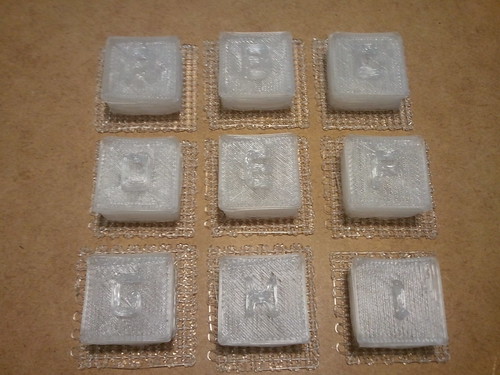
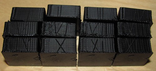
In order to help you identify the objects after they have printed, the objects to be printed are sequential block letters with the embossed letter on top. The idea is that the user looks at the printed letters, and decides which iteration has the best visual results. Looking back at the gcode, it is specified which letter block corresponds to each value, and the best performing value can be input into skeinforge. Using this process with any skeinforge parameters in question will allow you to tune you machine to the max!
How to Use Paraminator.py
Currently, the paraminator script is only functional via the command line. First verify that "paraminator.py" and the "test-objects" folder are both living in the ReplicatorG/skein_engines/skeinforge-35/skeinforge_application directory. The test-objects folder should contain 26 letter block stls.
You will also need python to be in your path: this means that if typing "python" doesn't start a python prompt (which, btw, can be exited by typing in the command "quit()" if yours works) it will have to be added. Linux and OS X are probably OK, but windows users will likely need to edit their "Environment Variables" in the "Advanced" section of "System Properties," which can usually be accessed by right-clicking "Computer" or "My Computer" and choosing "Properties." Add the name of the folder where python is installed, often C:\Python27 or something similar.
Now decide which setting in skeinforge you would like to explore, and take note of exactly how it appears in skeinforge, and which plug-in it belongs to. For instance, if you want to change the layer thickness, it appears in skeinforge as "Layer Thickness (mm)" (capitalization matters) and it is part of the Carve plug-in.

Open up the Terminal, and navigate to the ReplicatorG/skein_engines/skeinforge-35/skeinforge_application directory.

The layer thickness test example will be carried out through the entire paraminatin' process. Before the script is run, there are 6 things that need to be specified:
- file - this is where you locate the plug-in file. For the example above, the carve.csv file would need to be specified. In skeinforge 35, the csv files are located deeper within the skeinforge_application directory at: prefs/SF35-Thingomatic-ABP/profiles/extrusion/ABS/carve.csv
- parameter - this is the parameter that is going to be changed, and it needs to be written with quotations exactly how it appears in skeinforge: "Layer Thickness (mm)"
- start - this is the starting value for the parameter you want to explore. It's a good idea to have a starting value below your expected ideal value, so that it will be clear when you reach the ideal value. For the layer height test, we will choose: 0.32
- end - this is the ending value for your parameter. It should be higher than expected. For the layer height test, we will choose: 0.40
- increment - this dictates how many objects will be printed in your test. For the layer height test, if an increment of 0.04 is chosen, it would create 3 objects: 0.32, 0.36, and 0.40. If we were to choose an increment of 0.02, it would create 5 objects: 0.32, 0.34, 0.36, 0.38, and 0.40. To be thorough, lets choose an increment of 0.01.
- output - this is where you specify the file name you want for the test. The output will be a single gcode file that queues up all the incremental parts into a single print session on the ABP. The output gcode file can also be found in the skeinforge_application directory. For the layer height test, we will choose our output name as: ABS-layerheight-test.gcode
Now go back to the terminal, and get ready to execute the paraminator script. The six specifications above will all be typed into the command line to execute the script:
python paraminator.py --file=prefs/SF35-Thingomatic-ABP/profiles/extrusion/ABS/carve.csv --parameter="Layer Thickness (mm)" --start=0.32 --end=0.4 --increment=0.01 --output=ABS-layerheight-test.gcode
Note: the "--" above is actually two hyphens

The script will start generating your objects.


The script is finished and you can now open the gcode in ReplicatorG, and start testing! In the beginning of the gcode, there is a commented out reference table for determining which value corresponds with each letter block.

Good luck, and happy paraminating!